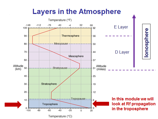
In this module we will be focusing on radio frequency propagation in the troposphere (see figure below), the lowest part of the atmosphere. We will be starting with some basic meteorological principles that you will need to understand to make sense of the later material. Then we'll continue on to ducting formation, and look at refraction effects on global to local scales.
Pressure, Temperature, and Humidity are the basic atmospheric variables.
Variations on temperature:
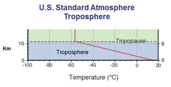 |
The U.S. Standard Atmosphere is often used to estmate Rf propagation conditions. It represents average temperature and pressure values with temperature decreasing at a rate of 6.5C / Km. It also assumes that there is no water vapor, which is unfortunate because it is the water vapor gradients that have the biggest effects on Rf propagation. |
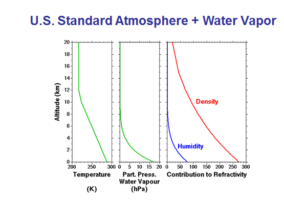 Image courtesy of http://mst.nerc.ac.uk/refract_index.html |
From now on, when referring to a |
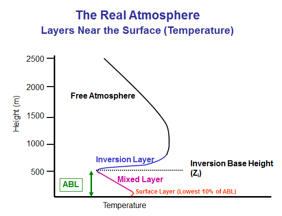 |
In contrast to a standard atmosphere, the real atmosphere will be more complex and have more layers. This chart shows a temperature profile (temperature vs height) where there is an atmospheric boundary layer (ABL) capped by a temperature inversion.
|
|
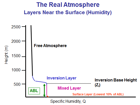
Similar to the above temperature profile, this is a chart of Specific Humidity, Q, (x-axis) vs. elevation (y-axis).
|
Next, we'll look at the frequency ranges and some of the military uses within these ranges.
| This diagram shows various Rf frequency bands and the propagation modes associated with them. In the earlier section we discussed ground waves and sky waves because these are the important modes for HF and lower frequencies. Now, the focus is on spacewaves which is the normal propagation mode in the VHF-EHF bands. They do not necessarily occur only in space - they can also travel in the troposphere. Although space waves at close ranges are line-of-sight, at longer ranges vertical variations in pressure, humidity and temperature can have strong effects, it is these effects that we focus our attention on. | 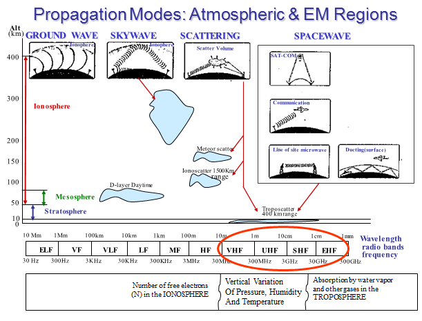 |
 |
| ||||||||||||||||||
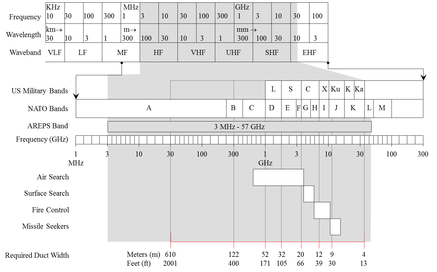
| This diagram shows how the frequency bands are further subdivided into small bands. Some of the military uses of various frequency bands are shown. You may be familiar with the US Military Bands for SHF (microwave) and higher (millimeter wavelength) frequencies. i.e L, S, C, X, Ku, Ka bands. If you will be using equipment such as radars or communication systems, knowing these bands is helpful since they are often referred to, instead of an actual frequency. | |||||||||||||||||||
Understanding how refraction works is key to understanding atmospheric effects on radar, communications and other EM systems. Refraction is the term used for the bending of radio waves. In outer space, with no atmosphere, radio waves propagate in straight lines. In the earth's troposphere, radio waves are bent, due to interactions with the bounded electrons in air molecules.
Refraction is generally the most important effect on radar propagation, communications and other Rf systems. In the troposphere, refraction is caused by spatial variations in temperature, pressure and humidity, with humidity being the most important.
| Why is water vapor so important in Refractivity? | 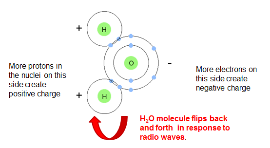 |
Water vapor is the only significant dipole molecule (one side is positively charged. the other is negative) in the atmosphere. Because water vapor molecules flip in response to VHF-SHF frequencies, they are effective re-emittters and therefore have a strong effect on the index of refraction. VHF-SHF EM radiation bends toward regions of higher humidity, as measured by the vapor pressure, e. |
|---|
Refraction depends on the index of refraction, n, which is defined as the speed of light in a vacuum (such as outer space), c, divided by the phase speed, v.
n = c/v
In the troposphere, the phase speed of the radio waves, v, is less, which causes the index of refraction, n, to be larger as compared to the ionosphere. Radio waves (or rays) bend towards regions of higher refraction, or higher n values.
Because n is approximately 1 followed by a number of zeros (e.g. 1.000345) before the significant digits, we introduce a new variable N which is defined as
N = (n-1) x 106
N is known as refractivity. It is the gradient of N, that is the change in N with height, that is important in determining how much the rays are bent.
| Good news: there is none! |
We saw in our discussion of the ionosphere how refraction from free electrons depends strongly on frequency. In the troposphere, bounded electron refraction in the VHF to SHF frequency bands is the same for all transmissions in this range. This is very useful, because it means that once an index of refraction n, has been determined, it does not have to be adjusted for different frequencies.
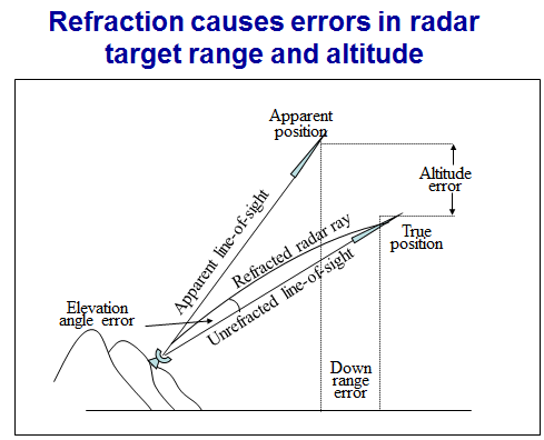 |
In this figure we see the effects of refraction. To the radar in the hills, the target appears to be higher and closer than it really is. |
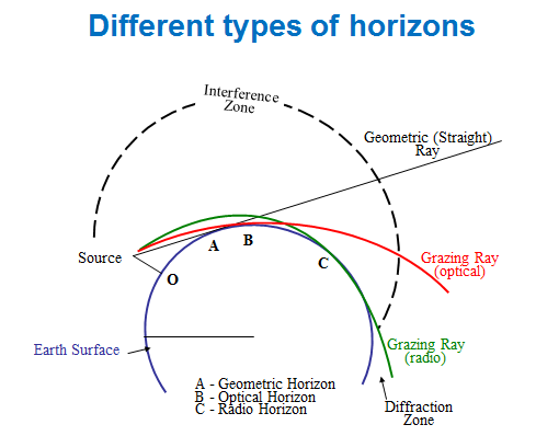 |
The earth's curvature is important for considering rf propagation, especially over the flat ocean. From a source above the surface such as a radar at location O, a straight line would graze the earth at location A. But on a clear day the visible or optical horizon, point B, is a further distance from the source. In typical atmospheric conditions radio waves bend more than light and therefore the radio horizon, point C is further form the source than either the geometric or optical horizons. Therefore in most situations, radars and radio have ranges over the apparent visible horizons. |
| - No atmosphere: If there were no atmosphere or diffraction then EM radiation would travel in a straight line. In this case the distance d (transmitter to geometric horizon) and the distance d2 (horizon target or receiver) are represented by the two equations shown. In this case only the heights of the transmitter and target (or receiver) and the Earth's curvature (as represented by 1/earth's radius) affect range. The subscript 1/2 indicates the square root of the bracketed quantity. | 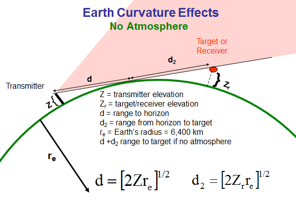 |
| - Standard atmosphere: When an atmosphere is present, the radio waves bend, so that the equations in the previous slide are not valid. However, if we assume that the gradient of N (change in N with elevation) represents a standard atmosphere, we can define an effective earth radius as 4/3 of the actual earth radius:
reff = (4/3) re and use this to create a simple formula for determining the range to the radio horizon: d = (2zreff)1/2 This is called the 4/3rds earth radius assumption and it is often used by engineers to estimate radar ranges. This is based on a standard atmosphere. So now when you hear someone say they are using the 4/3rds earth radius assumption, that means they are assuming the radio signals are propagating through a standard atmosphere. Engineers like the 4/3 earth's radius assumption because the radio horizon can be calculating with such a simple formula. Here's a simple example of a calculation estimating the propagation range assuming a standard atmosphere: reff = (4/3) re = (4/3) * 6300 km = 8400 km d = (2*z * reff)1/2
Note: The factor 130 applies to units of km; if using other units such as feet or miles, that factor must be adjusted. |
|
| - Real Atmosphere
A standard atmosphere represents average conditions and so if nothing else is known about the atmosphere, assuming it is standard is an easy way to make a best guess at radar or radio ranges using the formula shown above. However, for any actual situation, conditions are rarely average and may be greatly different from average. In these cases there is no simple formula to describe the radar or radio ranges and computer programs need to be used to estimate ranges. By considering atmospheric effects, considerable more accurate range predictions can be obtained. This is what the rest of this module is about.
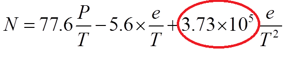
In the atmosphere, refractivity is affected by temperature, humidity and pressure as follows:
The large number in the red circle is much larger than any of the other coefficients, which means that it is the humidity variable e that has the largest effect. You will never need to use this equation manually (unless you are programmer), as computer programs such as AREPS or JSAF do the calculations for you. |
|
Trapping |
|
|
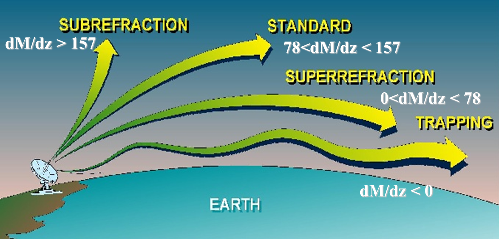
If the curvature of an EM ray is larger than the earth's curvature (i.e. more downward), then radiation will not escape into space but will be refracted down toward the earth's surface. When dN/dZ < -157 km-1 or -0.157 m-1, then a trapping layer exists, and communication and radar ranges will be greatly increased within and below that layer in a region called a duct. |
 dN/dZ = -157 km-1 represents a curve that matches the curvature of the earth. If it's less, rays are trapped; if it's greater, rays escape into space. |
|
If you are interested in ducting, clearly you need to identify regions where the gradient of N is less than -0.157 m-1, but this is difficult to do by visual inspection of a vertical N plot.
We make identifying ducts from profile plots much easier by using M, instead of N, where Regions of ducting can be clearly identifed when looking at a graph of M vs. Z since the gradient will be negative, i.e. the M value decreases as you go up on an elevation vs. M plot. Needs plot showing M and N. |
|
The equation for the Modified refractivity, M, is given by
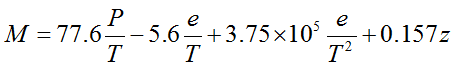 where T is temperature in K, P is atmospheric pressure in mb, e is vapor pressure in mb and z is height above the surface in meters. You will notice that this equation is identical to the equation for N, except for the last term. |
Refractivity classes |
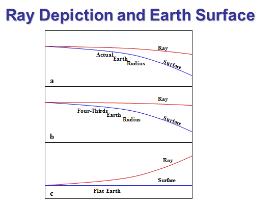 |
Programs that display Rf propagation such as AREPS use different types of representations of the earth's curvature. You should be aware of which type you are looking at -- it should be stated somewhere. The three most common types of displays are true earth radius, 4/3 earth radius, and flat earth (infinite radius).
As shown in the figure to the left: Figure a. True Earth: If actual curvature of the earth is depicted to scale, then an EM ray in a standard atmosphere will appear to bend downward, but not as much as the earth. Figure b. 4/3 Earth: If the curvature is depicted as 4/3 of the actual radius, then an EM ray in a standard atmosphere will appear to travel in a straight line. Figure c. Flat Earth: If the earth is depicted as flat, EM rays in a standard atmosphere will appear to curve upward. Most of the displays used for this course use a flat earth assumption, so the rays appear to bend upward (except in ducting cases, to be discussed later) compared the earth's surface as shown. |