Development of the Ice Cavity Profiler
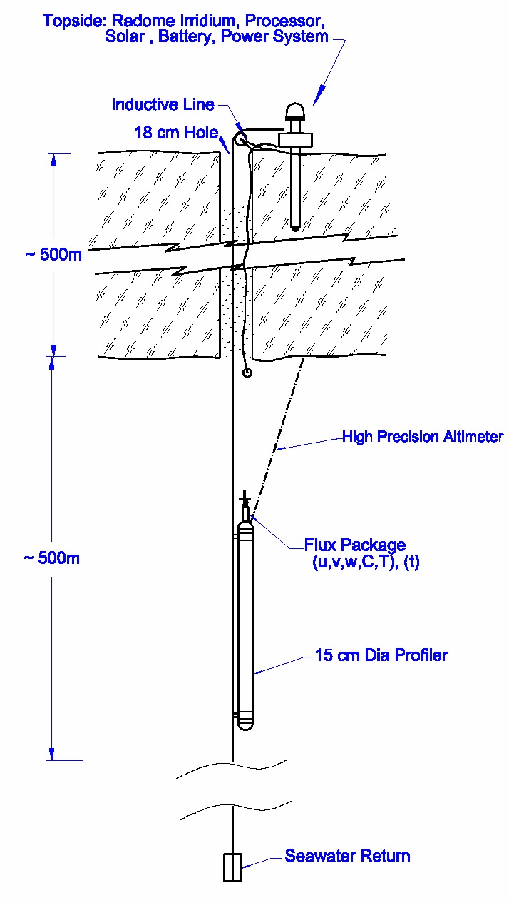
The proposed Small-hole Ocean Flux Profiler (SOFP, see figure), is based on polar-proven designs miniaturized to fit through a (17cm) access hole drilled through the ice shelf. It moves vertically along a taught line spanning the ocean cavity and reports data and receives sampling instructions from a satellite communication system on the ice-shelf surface. As described above, after development and testing in 2008-2009, one SOFP will be deployed at the PIG in the 2011, with three in the following (2012) field season.
The SOFP will be instrumented with a small format ocean turbulent flux package based on micro-powered ocean flux sensors that have been used successfully over the last four years in the North Pole Environmental Observatory under NSF funding (http://www.oc.nps.navy.mil/~stanton/fluxbuoy/). The profiler package will typically move from 3m below the ice base to near the sea bed every other day gathering a temperature, salinity and current profile, then park and the sample ocean fluxes through the following tidal cycle before continuing the profile/parking cycle. Profiler ice-ranges measured by an acoustic altimeter on the top of the profiler will be used with a high precision pressure sensor in the profiler and a surface barometric pressure sensor in the top-side package to measure ice melt rates with ~2 cm resolution, and determine where to park the SOFP for sub-ice boundary layer flux measurements. The profilers will have default sampling strategies and two year-capacity internal buffering / storage in the event that there are problems with the satellite communications and logging system on top of the glacier.
|
Cartoon diagram of the Small-hole Ocean Flux Profiler to be deployed in the ocean cavity below the Pine Island Glacier. Full resolution image
 |
|
Completed Design and Test Functions
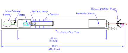
The complete internal and main body of the profiler has been designed, and weight, buoyancy and battery power budget have been modeled. A hydraulic fluid pump, internal reservoir and external bladder are used to vary the net buoyancy of the profiler to allow it to profile up and down the tether cable
Schematic diagram of the Small-hole Ocean Flux Profiler.
 |
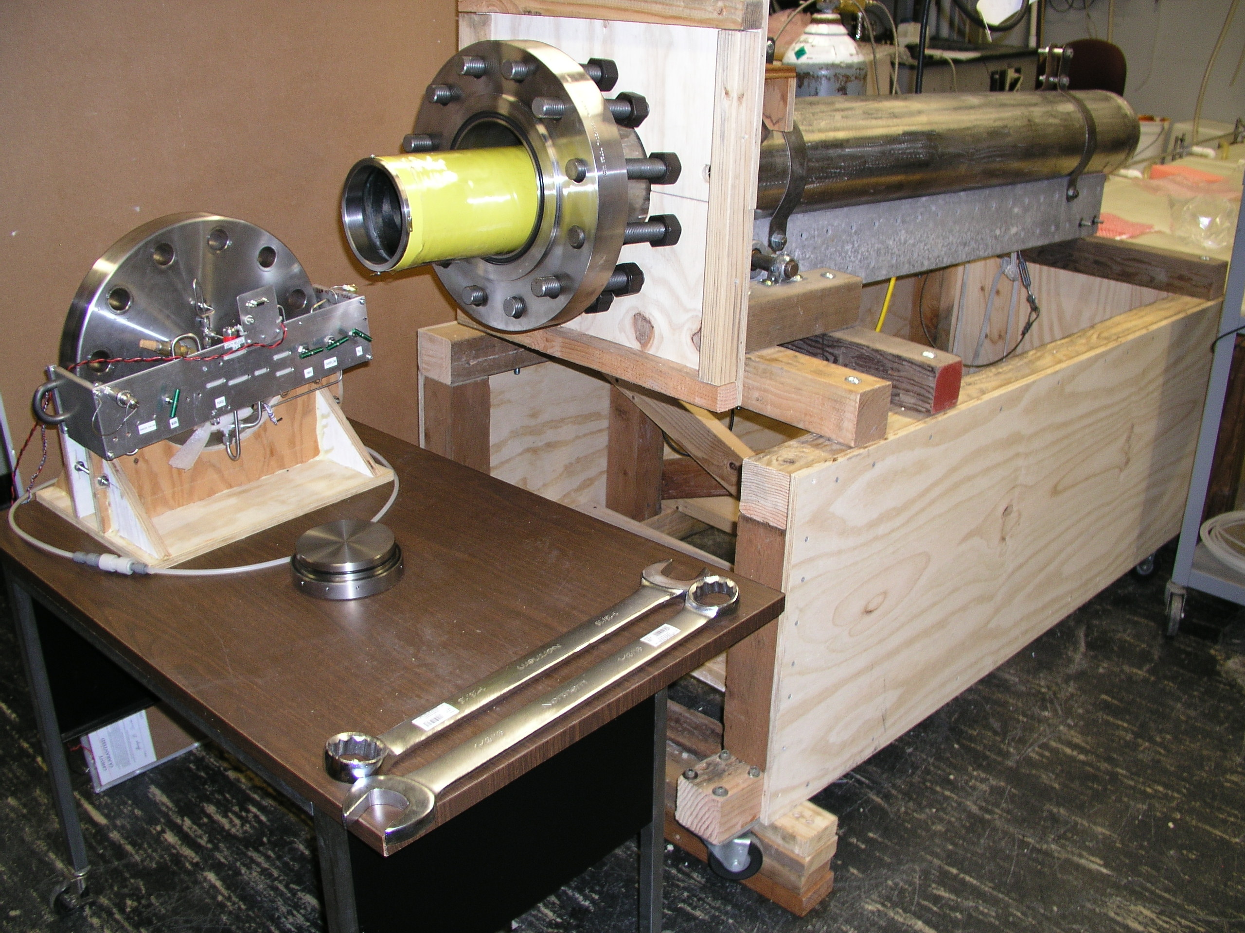
A custom underwater housing was designed, and tested initially using a finite element 3D model in the Solid Works CAD system. Two prototype housings have been constructed using a custom carbon fiber tube with titanium inserts.
The electronics design has been completed and the primary data acquisition and control board extensively tested. Each test has exercised a software module that will be used in the final profiler code.
|
A custom made pressure test vessel was purchased and configured. This test vessel is long enough to accommodate the complete profiler package for final pressure cycling of the complete instruments. It has now been used to perform pressure testing of of the profiler and sub-assemblies, including the buoyancy engine and the brake.
|
|
|
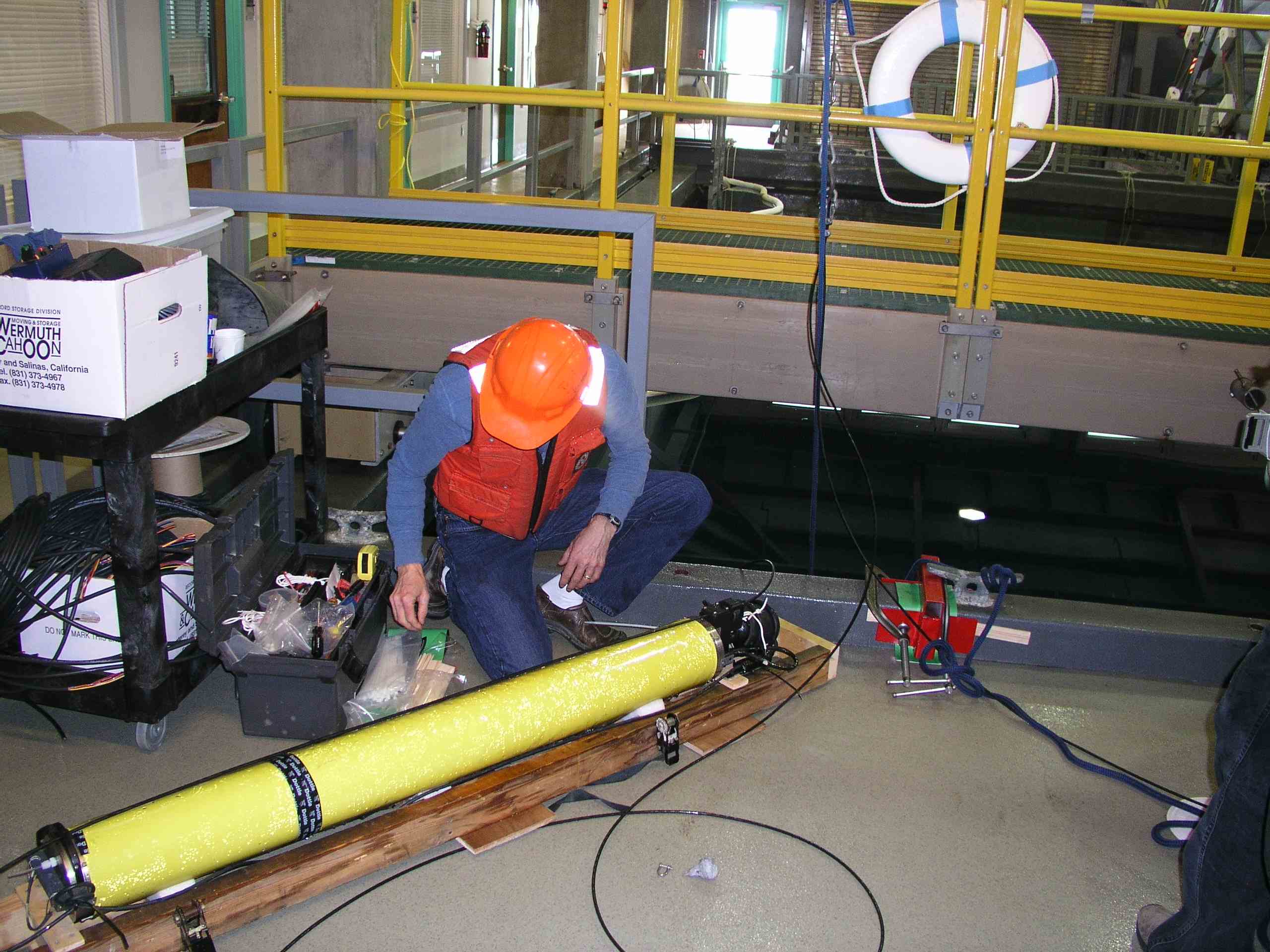
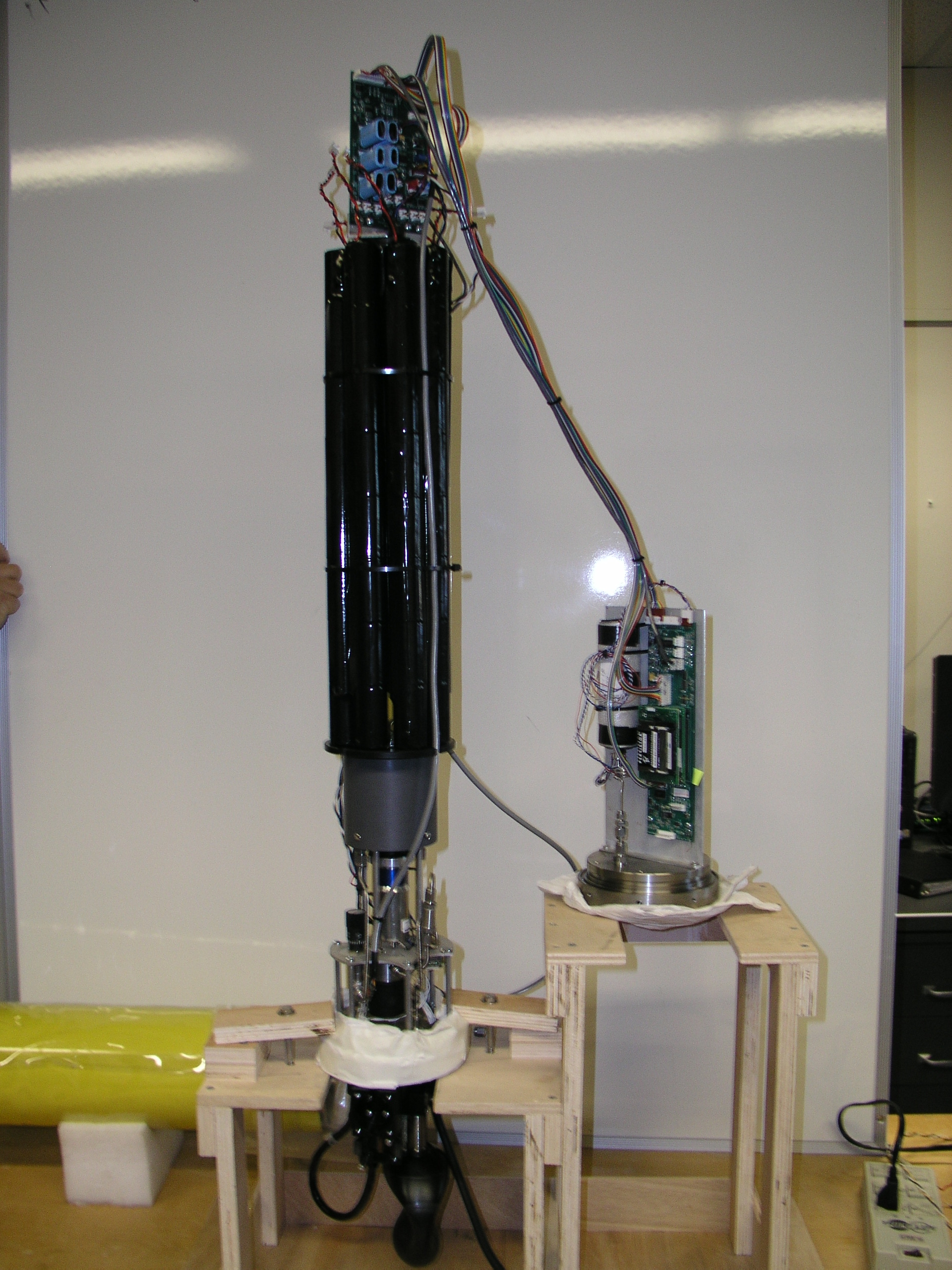
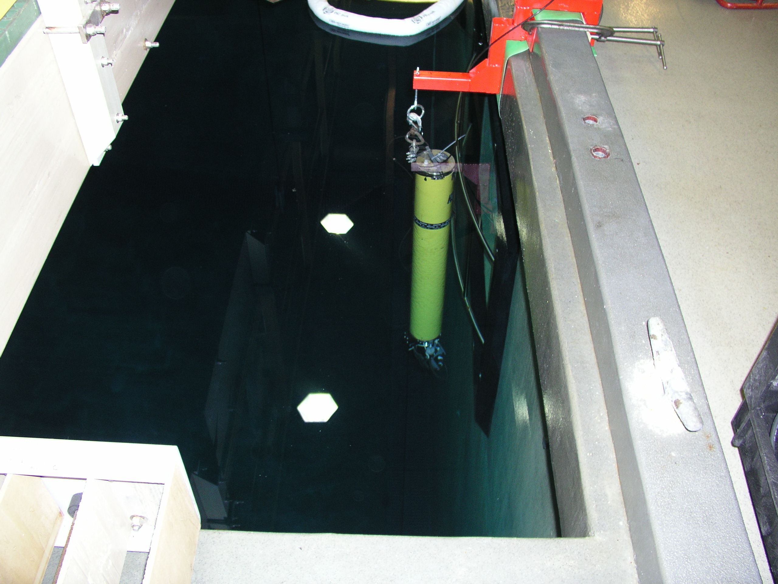
One profiler has been completely assembled in preparation for initial profiling tests in the deep test tank at the Monterey Bay Aquarium Research Institute.
|
|
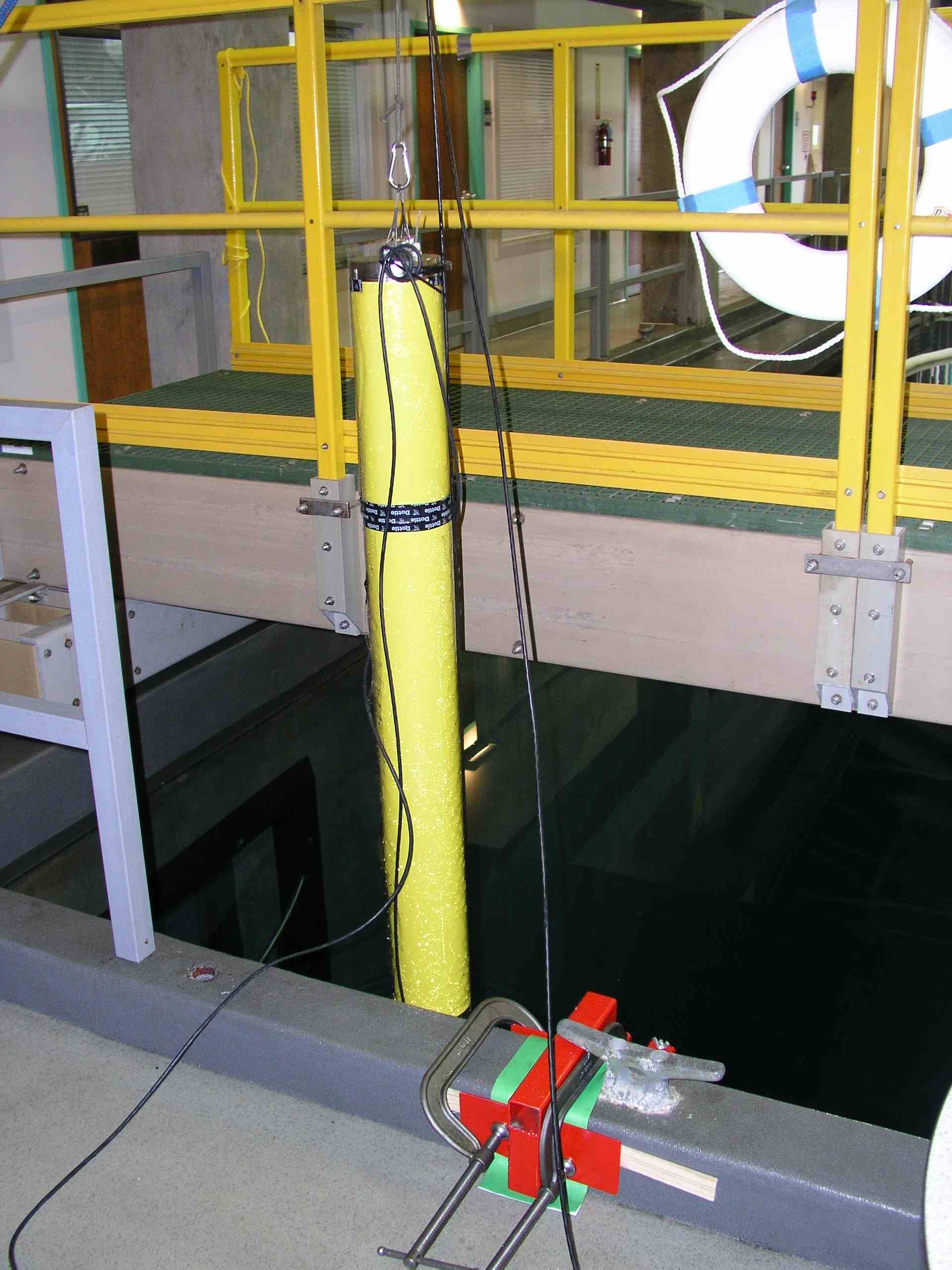
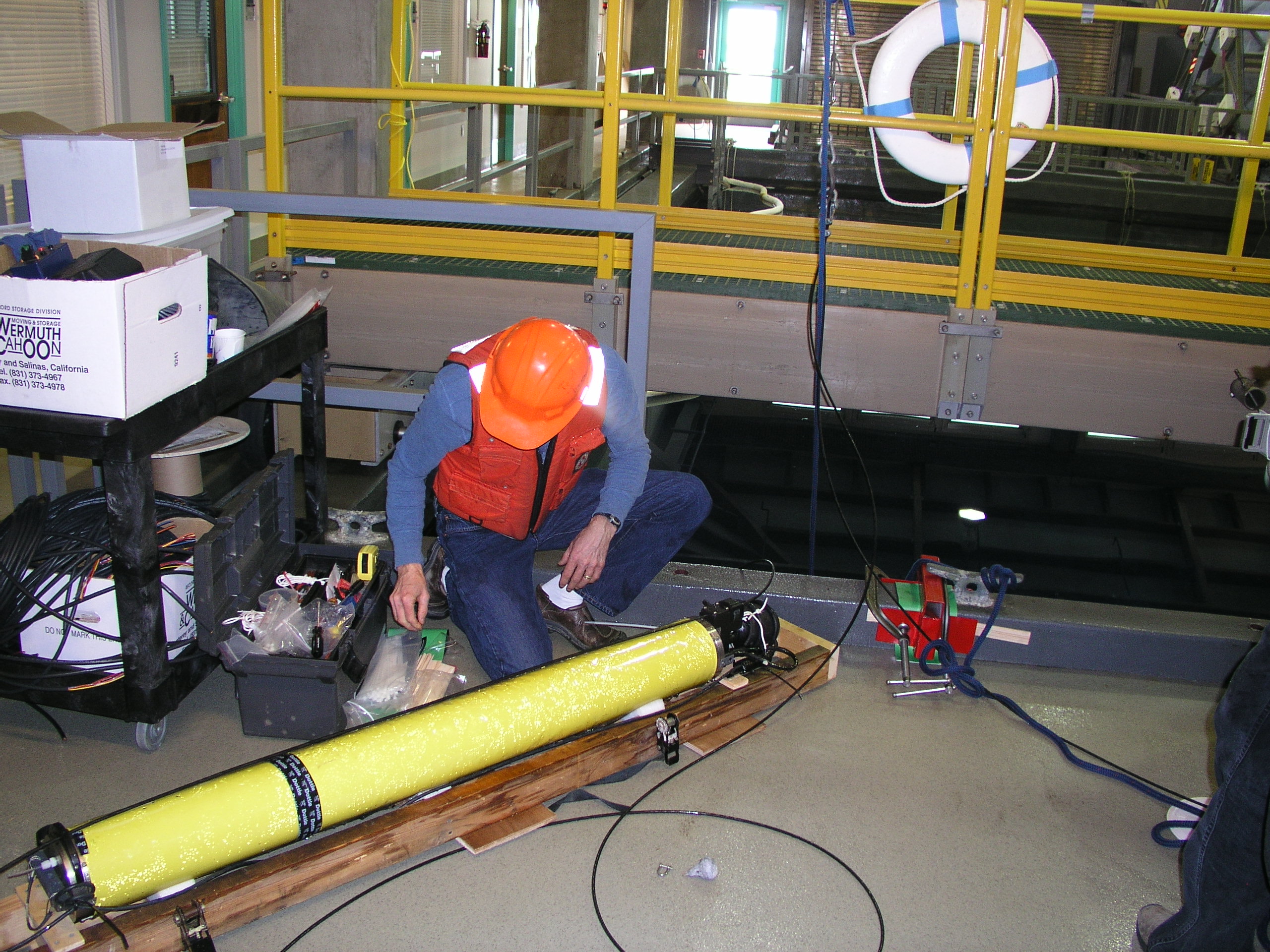
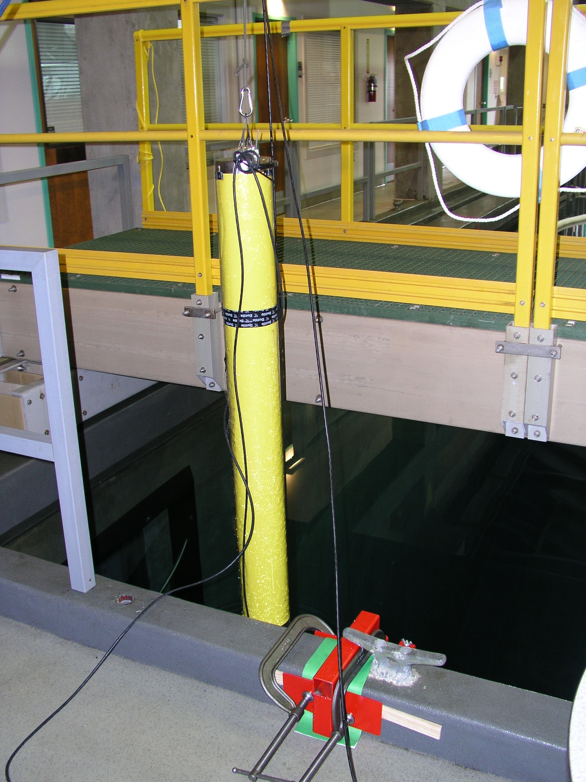
Testing of the buoyancy engine on the the prototype profiler was completed in the 10-m deep test tank at Monterey Bay Aquarium Research Institite (MBARI) in winter and spring of 2009.
|
|


