Naval Postgraduate School OC3902
FUNDAMENTALS OF MAPPING, CHARTING,
AND GEODESY
Lab8 (GPS Lab A): GPS RESEIVER (Field)
This lab is intended to have you gain some familiarity with GPS equipment and it’s uses and limitations.
Lab8 is divided up into 4 tasks. Each lab group will be assigned to start at a different task to avoid ‘clumping’ of the lab groups.
Task 1. Map
A. Provided to in this task are a United States Geological Service (USGS) topographical Quadrangle map, Mechanical Dividers, Mechanical Scale, Ruler and rolling parallel straight edge.
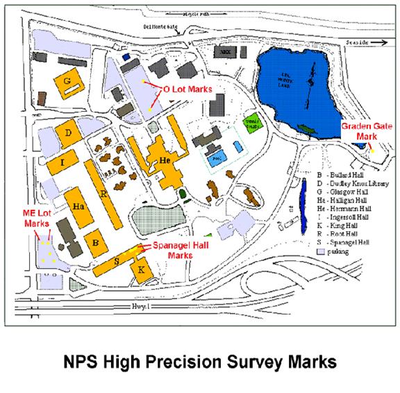
B. You are to find the Northern most corner of Spanagel Hall on the Map.
Tasks 2-4 Basics.
For the following 3 tasks, there are some instruction commonalities to each that I will describe first and only once, rather than reiterating them for each task. The commonalities all have to do with how to operate the equipment.
Using the Mobile Mapper GPS (here after just referred to as the ‘GPS’). Also refer to the ‘Getting Started Guides’ that are in each back pack
A. Turning the GPS on is a simple matter of pressing the red PWR button. To get to a functioning window, use must press enter to get past the license and warning screens. To turn off, press the red PWR button once and wait 5 seconds.
B. Go to the display window, by pressing the NAV button to change windows that shows the number of satellites. This window will show you how many satellites are being received and used for position computation. The ring with concentric circles shows the Space vehicle # (satellite) and when highlighted that it is being received. The position of the numbers also represents the approximate location on the horizon of where the satellites are. Below in the lower portion of the window is the signal strength of each of the satellites. If the satellite strength bar is hollow, it being received but not used for calculation. Additionally this is WAAS (Wide Area Augmentation System) enabled GPS receiver. If WAAS corrections are being received, a ‘W’ will appear near the Concentric Circles in the upper part of the window.
C. Now go to the display window that shows the Coordinates of your receiver’s location. It will also display the time and date. In this window by pressing the center button with arrow keys left or right you can toggle to another window that displays just your coordinates, in 2 different coordinate systems. I have set up these GPS receivers to have WGS 84 geodetic as the primary coordinate system and UTM NAD83 as the secondary. (This can be changed, see the manual).
D. Logging data is relatively easy. Press the LOG button to begin recording data. If this is your first task using the Mobile Mapper GPS, Select the option to ‘Create a New Job’ and hit the Enter button. Otherwise select ‘Open Existing Job’ your previously created job. If creating a job, you will have to give a name to the job using the arrow keys to select letters on the screen followed by the hitting the Enter button. Once done, select ‘OK’ on the screen and hit the Enter button.
E. You will now have to select a feature library. The feature library has essentially 3 elements. The type of feature, the Attributes of the feature and the Values corresponding to the attributes. In our case we are going to use the pre-made library called ‘Generic’.
F. If you have opened an existing job, you will have to press the log button again to actually get data. Now a window should appear with the selections of Point, Line or Area. Select, by pressing the enter button, which one depending on which task you are doing. NOTE! The moment you make this selection the GPS receiver will start logging data. Be sure you are you want to be!
G. Note that while the data is being logged, you will get a readout of the number of satellites being used and the PDOP or Position Dilution Of Precision. A lower PDOP number is better, with fewer than 4 &5 being good and over 10 bad. If you are getting numbers over 10 check your surroundings and make note of them.
H. While the data is logging you can add information to the data being taken. This is done by pressing the enter button when the comment portion is highlighted. Again a keypad arrange will appear and you can enter information that will allow you to recognize this feature from others. When done move the highlighted section to OK and press enter.
I. When you are done logging data, highlight the ‘close’ and press enter.
J. To close a job, press the MENU button and select close. Then press the Enter button. Note than when doing this it finalizes your data logging.
K.
If you accidentally close a job early, you can continue
to add to it by opening it as described earlier, or by using the menu button.
In fact, use only 1 job name for this lab, as it will simplify the later steps.
Task 2.
Record Location of the Northern corner of Spanagel Hall (Point).
A. Using the gear assigned to you. Go up to the roof (level 6) of Spanagel Hall and go to the northern most corner of the building (Closest to Herman Hall).
B. Turn on your Mobile Mapper GPS receiver as well as the Differential receiver. When turning on the Mobile Mapper, Press the Enter button until you are no longer asked questions on the screen.
C. Once in position check the number of satellites being tracked and whether or not WAAS & DGPS is being used.
D. LOG this location as a Point feature. Log this location for at least 5 minutes. Stay put! Enter a comment that reflects the location and length of the logging of data.
E. Log another Point feature in the exact same location, this time for only 1 minute with the differential beacon receiver turned off. Again enter an appropriate comment that reflects this location and length of the logging.
F.
As you will be comparing these two point locations to
your map read locations and to the reference value given below, make
note/estimate of how far and what
heading you are from the actual corner
of the building (You didn’t go past the railing to the edge did you?).
Task 3 ME
park lot (Line)
A. Go to the ME parking lot and find the two geodetic markers ME-PL-1 and ME-PL-3 placed in the ground in the parking lot (See the Attached Map for approximate locations). They are silver discs about 3” in Diameter with markings in them.
B. At each location, log a ‘Point’ feature for 5 minutes. Make sure to make a comment for each that reflects the location, such as ME-PL-1.
C. At one of the markers, turn off the Differential beacon Receiver, and log a ‘Point’ feature for just 1 minute.
D. Now log a ‘Line’ Feature between the two points. Once you open the feature just start walking between the two markers. Make sure to enter an appropriate comment, such as ME-PL-1&3. Close when done between the two points
Task 4. Area
around the redwood tree (Area).
A. Near the ME parking lot and just a bit south of the ME auditorium (close to the exit gate) there is a lone redwood tree in a grass area surrounded by concrete walkways. The shape is approximately triangular. Find this area.
B. Now log the ‘Area’ feature. Once you select this feature and the logging has begun, walk around the perimeter back to where you began. Enter a comment such as Redwood. Close when done with feature.
Down Loading from
A. Go to PC lab login your account, copy lab8 from \\lrcapps\common$\OC3902\FY09Qtr1 to your local working space. -> lab8 -> Mobile Mapper Office, click “mmoffice” to start Mobile Mapper Office.
B. Under the ‘File’ pull down in the top menu bar, select ‘Download GPS’. A large screen should appear. The left hand side of the window will be the files that are on the GPS and the right hand side the files on the PC. Notice that nothing is in the GPS yet, as you have not connected to the GPS yet. Navigate the right hand side such that it is in a directory on your H: drive that will be where you store your Lab 6 stuff.
C. Hook up the GPS unit to the computer using the provided Serial cable. This will require you to disconnect it from the Differential Beacon receiver. The serial port on the back of the computer is a 9 pin D connector and will have a mating sex opposite of the connector on the cable. Turn on the GPS receiver.
D. From the menu bar pull down named ‘File’ select connect. The software will automatically search for the correct serial communications protocol. The right hand side of your MobileMapper Transfer window should fill in. Hopefully if you collected data appropriately, a Name that gave the job for the task work has now appeared.
E. Highlight the file with your job name on the left and then from the menu pull down bar select ‘Move to’. The file should then move over to your selected location on the left part of the window. Once done you can close this window.
F. Now using the Mobile Mapper Office software, examine each of the items you logged. You should have 5 points, 1 line, and 1 area. By clicking on the item, the display in the left window will give you a summary of the data taken. You can zoom in and out by clicking on the icons in the menu bar. To get back after zooming and panning to be able to select items for review, hit the escape key. Save this file in one of your working directories so you can come back to it later when writing up the lab.
Spanagel 6 -- on Level 6 outside door 2326 36 35 42.0811 -121 52 28.9768 2.10 Span_6_Level_6 ME Parking Lot 5011 36 35 39.34841 -121 52 37.98704 -19.41 ME_ParkLot_01_2001 5013 36 35 41.52147 -121 52 38.51908 -20.11 ME_ParkLot_03_2001
DGPS Site Status and Operating Parameters
|
Site Name |
|
|
Status |
Operational |
|
RBn Antenna Location |
37-11.2N, 122-23.4W |
|
REFSTA Antenna
Location (A) |
37-11.22481N,
122-23.39619W |
|
REFSTA Antenna
Location (B) |
37-11.20943N,
122-23.38603W |
|
REFSTA RTCM SC-104 ID
(A) |
266 |
|
REFSTA RTCM SC-104 ID (B) |
267 |
|
REFSTA Firmware
Version |
RD00-1C19 |
|
Broadcast Site ID |
883 |
|
Transmit Frequency
(KHz) |
287 |
|
Transmit Rate (bps) |
100 |
|
Signal Strength |
75uV/m at 180 NM |
|
|
|
How does DGPS work?
The GPS determined position of a
reference station is computed and compared to its surveyed geodetic position.
The differential information ... some systems use the error in fix position,
while others use individual satellite range errors ... is transmitted to user
receivers by radio or other means.
Why use DGPS?
DGPS accuracy and integrity are better
than GPS.
* Accuracy improvement (2drms): Positions
of 10 meters or better are achievable using DGPS (USCG signals) vs. 100 meters
or better for GPS (Standard Positioning Service)
* Integrity improvement: Provides an
independent check of each GPS satellite's signal, and reports whether it's good
or bad.
(Back to "Labs
List" page.)
Last Updated 30 Sept., 2008
POC: Peter Chu