Naval Postgraduate School OC3902
FUNDAMENTALS OF MAPPING, CHARTING,
AND GEODESY
Laboratory 2
Datum and Coordinate Conversions
Objectives:
- Understand the scale of errors when using positional coordinates in
different datums
- Understand the conversions from Geocentric Cartesian Coordinates to
Geodetic
- Learn how
to use the file processing of the GEOTRANS application
Introduction about GEOTRANS:
GEOTRANS (Geographic Translator) is an application
that allows you to convert geographic coordinates among a wide variety of
coordinate systems, map projections, grids, and datums. GEOTRANS runs in Microsoft Windows (95, 98,
and NT) and UNIX Motif environments.
The user interface of GEOTRANS consists primarily of a
single window. To convert coordinates,
select the coordinate reference frame and datum in which your coordinates are
defined, enter any associated parameters, and enter the coordinates in the
upper half of the window. Then select
the coordinate reference frame and datum to which you want the coordinates to
be converted, and enter any associated parameters, in the lower half of the
window. Click on the Convert:
Upper-to-Lower button, and the resulting coordinates will be displayed in the
lower half of the window. You can
convert additional coordinate sets from the same source by just entering the
new coordinates and clicking on the Convert: Upper-to-Lower button. You can change the coordinate reference
frame, datum, or parameter selections at any time. Also, you can reverse the roles of input and
output by using the Convert: Lower-to-Upper button. Currently, thirty-two different types of
coordinate systems, map projections, grids, and coding schemes are supported,
as well as more than two hundred different horizontal datums.
GEOTRANS can also be used to efficiently convert large
numbers of coordinates contained in text files.
The file format is very simple. A
multiline file header defines the coordinate reference frame and datum of the
coordinates contained in the file, including any associated parameter
values. Following the header, each line
contains a single set of coordinates, separated by commas. Spaces and/or tabs
may follow each comma, but they are not required. Using the GEOTRANS file
processing interface, you can select an existing file of coordinates to be
converted. You can then define the coordinate
reference frame and datum to which you want to convert the coordinates, along
with any associated parameter values.
Finally, you can specify the name and location of the output file that
is to be created. GEOTRANS then converts
all of the coordinates in the input file and creates the output file as a
single operation.
Pre-Procedures:
Copy lab2_datums folder with all the files to your local working space from
\\lrcapps\common$\OC3902\FY09Qtr1\lab2_datums
Open folder geotrans2.2.4, then double click the
application file geotrans2 to open geotrans software.
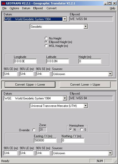
Geotrans Main Window
The
GEOTRANS main window will appear as shown in Figure. At the top of the window is the Title Bar,
which includes the standard window manipulation controls. Just underneath the Title Bar is the Menu
Bar, which contains five pull-down menus:
File, Options, Datum, Ellipsoid, and Convert.
The
main portion of the window is divided into upper and lower halves. Each half contains fields and other controls
the indicate the currently selected datum and ellipsoid, coordinate reference
frame, any associated parameters, and coordinates, as well as 90% circular
(horizontal), linear (vertical), and spherical error values. Separating the upper and lower halves of the
window are two Convert buttons. The
button on the left, Convert: Upper-to-Lower, converts the coordinates in the
upper half of the window to the coordinate reference frame specified in the
lower half of the window, outputting the results to the lower coordinate
fields. The button on the right,
Convert: Lower-to-Upper, does the opposite, converting the coordinates in the
lower half of the window, and outputting the results to the upper coordinate
fields.
To
convert a set of coordinates from one coordinate reference frame to another,
and/or transform it from one datum to another, follow these steps:
1.
If the desired input coordinate reference frame
type is not already displayed in the upper half of the window, select the
desired entry from the pull-down list.
The upper half of the window will be updated to display the appropriate
parameter and coordinate fields for the selected input coordinate reference
frame type.
2.
If the desired input datum is not already
displayed in the upper half of the window, select the desired datum using the
Datum pull-down list. (In the Windows
version, click on the arrow to open the list, use the scroll bars if necessary
to bring the desired entry into view, then select it by clicking on it. In the Motif version, click on the arrow
button to open the list, use the scroll bar if necessary to bring the desired
entry into view, then select it by double clicking.) The datum list contains global datums (WGS-84
and WGS-72) first, followed by seven-parameter local datums, and then by local
3-parameter datums, with each section in alphabetical order. When you select a datum, the Ellipsoid field
is updated to show the code and name of the ellipsoid associated with the
selected datum. (Note: you cannot select a specific ellipsoid
directly.)
3.
If the input coordinate reference frame has any
parameters associated with it (e.g., a central meridian), and the default
parameter values displayed in the upper half of the window are not the desired
values, change the parameter values by selecting the displayed values and
typing over them.
4.
Enter the input coordinates in the fields
displayed in the upper half of the window by selecting each field and typing
over its contents. . Optionally, specify
the accuracy of the input coordinates by entering values, in meters, in the
90%CE, 90%LE, and 90%SE fields, or by selecting an entry from the Sources
pulldown menu.
5.
If the desired output coordinate reference frame
type is not already displayed in the lower half of the window, select the
desired entry from the pull-down. The
lower half of the window will be updated to display the appropriate parameter
and coordinate fields for the selected output coordinate reference frame type.
6.
If the desired output datum is not already
displayed in the lower half of the window, select the desired datum using the
Datum pull-down list, just as for the input datum.
7.
If the output coordinate reference frame has any
parameters associated with it (e.g., a central meridian), and the default
parameter values displayed in the lower half of the window are not the desired
values, change the parameter values by selecting the displayed values and
typing over them.
8.
Click on the Convert: Upper-to-Lower
button. The output coordinates will be
displayed in the coordinate fields in the lower half of the window. The 90% circular, linear, and spherical error
values will also be updated.
Procedures
1. Transform a simple geodetic position
(Lat/Long/h) from
Wreck of the FRAM
The
Fram was a Swedish steamer built in 1897. In January 1941 she was enroute from
a. In the menu bar, select the Options Pull-down Menu, Geodetic Units, Degrees
options, select Degrees/Minutes.
b. Select the Input Datum as Ordnance
GB 1936,
c. Select the both Input and
output coordinates as Geodetic.
d. Select MSL Height (m).
e. In the Longitude Field, enter
“002 10.584W”.
f.
In the Latitude Field, enter “57
42.097N'”.
g. In the Height Field, enter 0.
h. Select the Output Datum as WGS84
i.
In the lower output box check the bubble “Ellipsoid Height”
j.
Press <Convert
Upper->Lower> at the convert bar.
2. Using GEOTRANS transform geodetic coordinates located in
Navigating using GPS with Korean maps and charts requires some
caution. Do the following datum
transformation with GEOTRANS to understand the scale.
a. In the menu bar, select the Options Pull-down Menu, Geodetic Units, Degrees options,
select Degrees.
b. Select the Input
Datum as WGS84.
c. Select Geodetic for both the input
and output geographic coordinates.
d. Check the bubble “Ellipsoid
Height”.
e. In the Latitude Field, enter “38N”.
f.
In the Longitude Field, enter “127E”.
k. In the Height Field, enter 0.
g. Ensure Tokoyo Datum (
h. In the lower output box check
the bubble “Ellipsoid Height”
i.
Press <Convert
Upper->Lower> at the convert bar.
3. Examine
a position in Geocentric Cartesian Coordinates and calculate geocentric
latitude and convert to geodectic coordinates
(X,Y,Z) = (-2737547, -4380990, 3728170)
Using
GEOTRANS, convert this Geocentric Cartesian Coordinate to geodetic
j.
In the menu bar, select the Options
Pull-down Menu, Geodetic Units, Degrees options, select Degrees.
a. Select the Geocentric
for the input coordinate.
b. Ensure WGS84 is selected in the top Datum box and bottom Datum box.
c. Select Geodetic for the output
geographic coordinate.
d. Press <Convert Upper->Lower> at the convert bar.
4. Examine a practical problem of transforming a
large set of geodata from one to another datum
Geotrans can also transfer geodata from text file to
text file in the certain format. The GEOTRANS coordinate file format is very
simple. A GEOTRANS coordinate file
contains a file header that specifies the datum and the coordinate reference
frame type of the input coordinates, including any associated parameter
values. The header is followed by sets
of input coordinate values, one set per line, with the individual values
separated by commas. Spaces and/or tabs may follow each comma, but they are not
required. The following example shows a GEOTRANS coordinate file containing
Mercator projection coordinates defined relative to the WGS 84 datum. The file header defines the coordinate
reference frame type, the datum, ellipsoid, and the projection parameters,
which for a Mercator projection include the
Example:
COORDINATES: Mercator
DATUM: WGE
#ELLIPSOID: WE
ORIGIN LATITUDE: 0 0 0.00N
FALSE EASTING: 0
FALSE NORTHING: 0
END OF HEADER
-503297, 4056709
490031, 4872921
331276, 5139284
221385, 5582934
113908, 5932832
-123456, 6123233
The
header of a GEOTRANS coordinate file consists of two or more lines, each
containing a key word or phrase which identifies the purpose of the line,
followed by a colon ‘:’, followed by a value.
The key words and phrases that can be included in a GEOTRANS coordinate
file header are:
·
COORDINATES or PROJECTION – This line identifies
the coordinate reference frame type of the coordinates in the file. Therefore, a line with one of these two key
words should be included in every GEOTRANS coordinate file header, and should
precede any lines which set map projection parameters. The associated value consists of a word or
phrase identifying the coordinate system or map projection, as follows:
-
Geodetic
-
GEOREF
-
Geocentric
-
Local Cartesian
-
MGRS
-
UTM
-
UPS
-
Albers Equal Area Conic
-
Azimuthal Equidistant
-
Bonne
-
British National Grid
-
Cassini
-
Cylindrical Equal Area
-
Eckert IV
-
Eckert VI
-
Equidistant Cylindrical
-
Gnomonic
-
Lambert Conformal Conic
-
Mercator
-
Miller Cylindrical
-
Mollweide
-
-
Ney’s (Modified Lambert Conformal Conic)
-
Oblique Mercator
-
Orthographic
-
Polar Stereographic
-
Polyconic
-
Sinusoidal
-
Stereographic
-
Transverse Cylindrical Equal Area
-
Transverse Mercator
-
Van der Grinten
·
DATUM –
This line identifies the datum for which the coordinates in the file are
defined. A line with this key word
should be included in every GEOTRANS coordinate file header. The associated value consists of a standard
3- to 5-letter datum code, as defined in the datum pull-down lists in the
GEOTRANS main and file processing windows (e.g. WGE, EUR-M, EAS, etc.)
·
ELLIPSOID
HEIGHT - This line specifies that any height values in Geodetic input
coordinates are measured relative to the selected ellipsoid surface. A line with this key word is optional in a
GEOTRANS input file header, and applies only to geodetic input coordinates. If it is not included, all geodetic height
values default to ellipsoid heights. The
GEOTRANS output file header will contain this line if the Ellipsoid Height type
has been specified with Geodetic coordinates.
·
GEOID/MSL
HEIGHT - This line specifies that any height values in Geodetic input
coordinates are measured relative to the EGM96 geoid model (if the
corresponding datum is WGS84) or mean sea level (MSL) surface (otherwise). A line with this key word must be included in
the GEOTRANS input file header if geoid/MSL height values are to be input. If it is not included, all geodetic height
values default to ellipsoid heights. The
GEOTRANS output file header will contain this line if the Geoid/MSL Height type
has been specified with Geodetic coordinates.
·
NO
HEIGHT - This line specifies that no height values are included with input
Geodetic coordinates. A line with this
key word must be included in a GEOTRANS input file header if geodetic height
values are not to be input. If it is not
included, all geodetic height values default to ellipsoid heights. The GEOTRANS output file header will contain
this line if the No Height type has been specified with Geodetic coordinates.
·
·
ORIGIN
LATITUDE – This line specifies the value of an Origin Latitude parameter, which
defines the vertical center of a map projection. It is used by most of the map projections
(Albers Equal Area Conic, Azimuthal Equidistant, Bonne, Cassini, Cylindrical
Equal Area, Gnomonic, Lambert Conformal Conic, Mercator, Ney's (Modified
Lambert Conformal Conic), Oblique Mercator, Orthographic, Polyconic,
Stereographic, Transverse Cylindrical Equal Area, and Transverse
Mercator). It is also used, along with
the Origin Longitude, and Origin Height parameters, to specify the location of
the origin of a Local Cartesian coordinate system. The associated value is a latitude value in
degrees, degrees/minutes, or degrees/minutes/seconds, and defaults to 0°N.
·
FALSE
EASTING – This line specifies the Easting, or X, coordinate at the origin of
the projection. It offsets the
projection coordinates, and is commonly used to avoid the need for negative
coordinates by setting the coordinate at the origin to a relatively high
value. It is used by all of the map
projections. The associated value is an
optionally signed real value in meters, and defaults to zero.
·
FALSE
NORTHING – This line specifies the Northing, or Y, coordinate at the origin of
the projection. It offsets the
projection coordinates, and is commonly used to avoid the need for negative
coordinates by setting the coordinate at the origin to a relatively high
value. It is used by all of the map
projections. The associated value is an
optionally signed real value in meters, and defaults to zero.
·
STANDARD
PARALLEL– This line specifies the value of the Standard Parallel parameter,
which defines a parallel along which the point scale factor of the projection
is 1.0. It is used by the Equidistant
Cylindrical projection. The associated
value is a latitude value in degrees, degrees/minutes, or
degrees/minutes/seconds, and defaults to 0°.
·
STANDARD
PARALLEL ONE – This line specifies the value of the 1st Standard Parallel
parameter, which defines a parallel along which the point scale factor of the
projection is 1.0. It is used by the
Albers Equal Area Conic, Lambert Conformal Conic and Ney's (Modified Lambert
Conformal Conic) projections. The
associated value is a latitude value in degrees, degrees/minutes, or
degrees/minutes/seconds, and defaults to 40°N.
·
STANDARD
PARALLEL TWO – This line specifies the value of the 2nd Standard Parallel parameter,
which defines a parallel along which the point scale factor of the projection
is 1.0. It is used by the Albers Equal
Area Conic, Lambert Conformal Conic and Ney's (Modified Lambert Conformal
Conic) projections. The associated value
is a latitude value in degrees, degrees/minutes, or degrees/minutes/seconds,
and defaults to 50°N.
·
LATITUDE
ONE - This line specifies the value of a first point latitude parameter, which
defines the latitude of the first point lying on the central line of an Oblique
Mercator projection. The associated value is a latitude value in degrees,
degrees/minutes, or degrees/minutes/seconds, and defaults to 40°N.
·
LONGITUDE
ONE - This line specifies the value of a first point longitude parameter, which
defines the longitude of the first point lying on the central line of an
Oblique Mercator projection. The
associated value is a longitude value in degrees, degrees/minutes, or
degrees/minutes/seconds, and defaults to 5°W.
·
LATITUDE
TWO - This line specifies the value of a second point latitude parameter, which
defines the latitude of the second point lying on the central line of an
Oblique Mercator projection. The associated value is a latitude value in
degrees, degrees/minutes, or degrees/minutes/seconds, and defaults to 50°N.
·
LONGITUDE
TWO - This line specifies the value of a second point longitude parameter,
which defines the longitude of the second point lying on the central line of an
Oblique Mercator projection. The associated value is a longitude value in
degrees, degrees/minutes, or degrees/minutes/seconds, and defaults to 5°E.
·
SCALE
FACTOR – This line specifies the projection Scale Factor parameter, which
defines the ratio between distances measured in the projection coordinate
space, and the corresponding distances on the surface of the reference
ellipsoid at the origin. It is used by
the Mercator, Oblique Mercator, Transverse Cylindrical Equal Area and
Transverse Mercator projections. The
associated value consists of a real number between 0.3 and 3.0. The default value is 1.0.
·
ORIGIN
LONGITUDE – This line specifies the value of an Origin Longitude parameter,
which, with the Origin Latitude and Origin Height parameters, specifies the
location of the origin of a Local Cartesian coordinate system. The associated value is a longitude value in
degrees, degrees/minutes, or degrees/minutes/seconds, and defaults to 0°N.
·
ORIGIN
HEIGHT – This line specifies the value of an Origin Height parameter, which,
with the Origin Latitude and Origin Longitude parameters, specifies the
location of the origin of a Local Cartesian coordinate system. The associated value is a real value in
meters relative to the ellipsoid surface, and defaults to zero.
·
ORIENTATION
– This line specifies the value of an Orientation parameter, which specifies
the clockwise angle from north to the positive Y axis of a Local Cartesian
coordinate system. The associated value
is a longitude value in degrees, degrees/minutes, or degrees/minutes/seconds,
and defaults to 0°.
·
LONGITUDE
DOWN FROM POLE – This line specifies the orientation of a Polar Stereographic
projection. The specified longitude
defines the direction of the negative Y axis of the resulting projection. The
associated value is a longitude value in degrees, degrees/minutes, or
degrees/minutes/seconds, and defaults to 0°.
·
LATITUDE
OF TRUE SCALE – This line specifies the scale of a Polar Stereographic
projection, in terms of the latitude at which the scale factor has a value of
1.0. The associated value is a latitude value in degrees, degrees/minutes, or
degrees/minutes/seconds, and defaults to 90°N.
The order of the lines in the header is arbitrary,
except that either the “COORDINATES” or “PROJECTION” line, which defines the
coordinate reference frame type, must come before any lines specifying
parameters. If the same key word or
phrase appears more than once, the value associated with the last appearance
will be the value used. The header is
terminated by a line containing the phrase ‘END OF HEADER’.
If any characteristic or required parameter is not
specified in the input coordinate file header, a default value is
assigned. The default coordinate
reference frame type is Geodetic, and the default datum is WGE (WGS 84). For each coordinate reference frame type, the
default parameter values used are the same default values that are displayed in
the parameter fields in GEOTRANS main window when that coordinate reference
frame type is selected.
Working
on a project for a major minesweeping exercise in the
a. Open GEOTRANS.
b. Select the File menu, Open option.
c. Navigate to your lab2_datums and select the gulflanes.dat
file.
d. Press <Open>; the GEOTRANS File Processing Window should be open.
e. In the Output Box, select Geodetic as the coordinate format.
f.
Press <OK>; the Save As
Window should be open.
g. Navigate to the folder lab2_datums and type gulflanes84.dat as the file name to
save.
h. Press <Save>; the GEOTRANS File Processing Waiting Window should
open.
i.
View the difference between gulflanes.dat and gulflanes84.dat.
Lab Results Turned in: Not Required
(Back to "Labs List" page.)
Last Updated 29 September, 2008
POC: Peter Chu